Preparing your 5A-75B
The 5A-75B needs to be modified before it can be used as a CNC motion controller. The most important changes are:
Adding pins for flashing the firmware onto the card (JTAG);
Removing the buffers.
Especially the last step requires the removal of several SMD-components from the card and migth require some experience with soldering these types of components.
Board overview
The image below shows an annotated view of the PCB, showing the JTAG-headers and the buffers. At this moment there are three known versions of these cards: v6.1, v7.0 and v8.0. The layout of these cards may differ between versions.
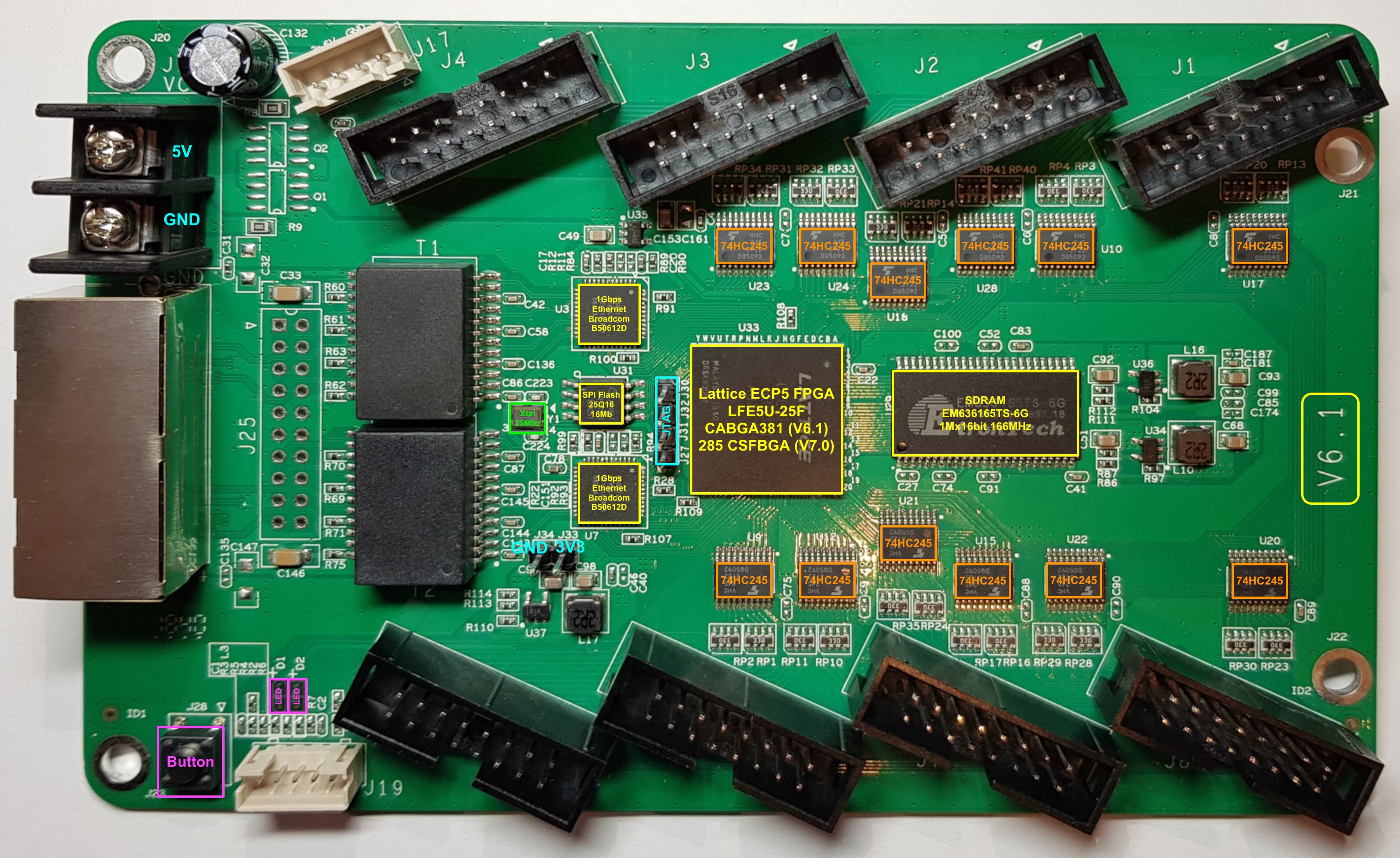
The main difference of the V8.0 card is the location of the JTAG-headers. The HUB75HAT is designed to accept all versions.
Adding JTAG-headers
The JTAG headers are not populated by default. Solder a 2-pin header at J33/J34 and a 4-pin header for JTAG next to the FPGA (J27, J31, J32, J30). For the function of each of the pins, see the hardware description <https://github.com/q3k/chubby75/blob/master/5a-75b/README.md>.
Removing the buffers
Warning
All buffers on the board convert the 3.3 V from the FPGA to 5V outputs. Leaving the wrong buffers on the board might drive the Raspberry-Pi GPIO with 5 V, leading to destruction of the Raspberry-Pi. Therefore it is strongly recommended to remove all buffers from the 5A-75B. The HUB75HAT is designed to run on 3.3 V and provides 5V tolerant buffers in order to protect the FPGA.
The buffers can be removed by any of the methods below:
desoldering;
cutting the legs of the ICs with a sharp knife and clearing the pads from the left-over pins.
One has to be very carefull